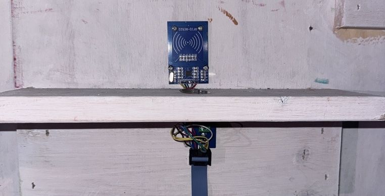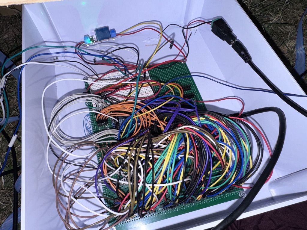
Each musical step includes two electrical components: a piezo vibration sensor and an RFID reader. The piezo requires two wires (GND and Signal), while the RFID reader needs seven (CS, SCK, MOSI, MISO, GND, RST, and 3.3V). By sharing the GND connection, each step requires 8 unique wires, adding up to 80 wires across all 10 steps.
At the start of the semester, I gave myself a week to complete the wiring. But I severely underestimated the complexity of managing that many connections at scale, and it ended up taking over a month.
My initial plan was to run individual wires from the Arduino Mega to each RFID reader and vibration sensor pin. However, this raised two major concerns:
I approached my senior capstone advisor with these concerns, and he suggested using ribbon cable to connect each peripheral step to a central protoboard. If a step failed, its cable could be easily detached, making component replacement quick and straightforward.


As a result, wiring up a single step became an hours-long process. For each one, the ribbon cable had to be carefully measured, cut to length, and crimped onto connectors. On the step side, eight wires were measured, cut, stripped, soldered to their respective components, and threaded through small holes in the step platform. The RFID reader was mounted to the wall, and the piezo sensor was adhered directly to the step.
On the protoboard side, pin headers were cut and soldered in place, both for each ribbon cable and for the shared signals (MISO, MOSI, SCK, RST, GND, and 3.3V). Only after all of this could the sensors be connected to the Arduino Mega for integration testing.
If I had done this alone, it would have taken days. But fortunately, other team members were eager to help. I created a series of step-by-step instructions to guide them through assembling and testing each component. Here’s an example for the piezo vibration sensors.