Musical Steps
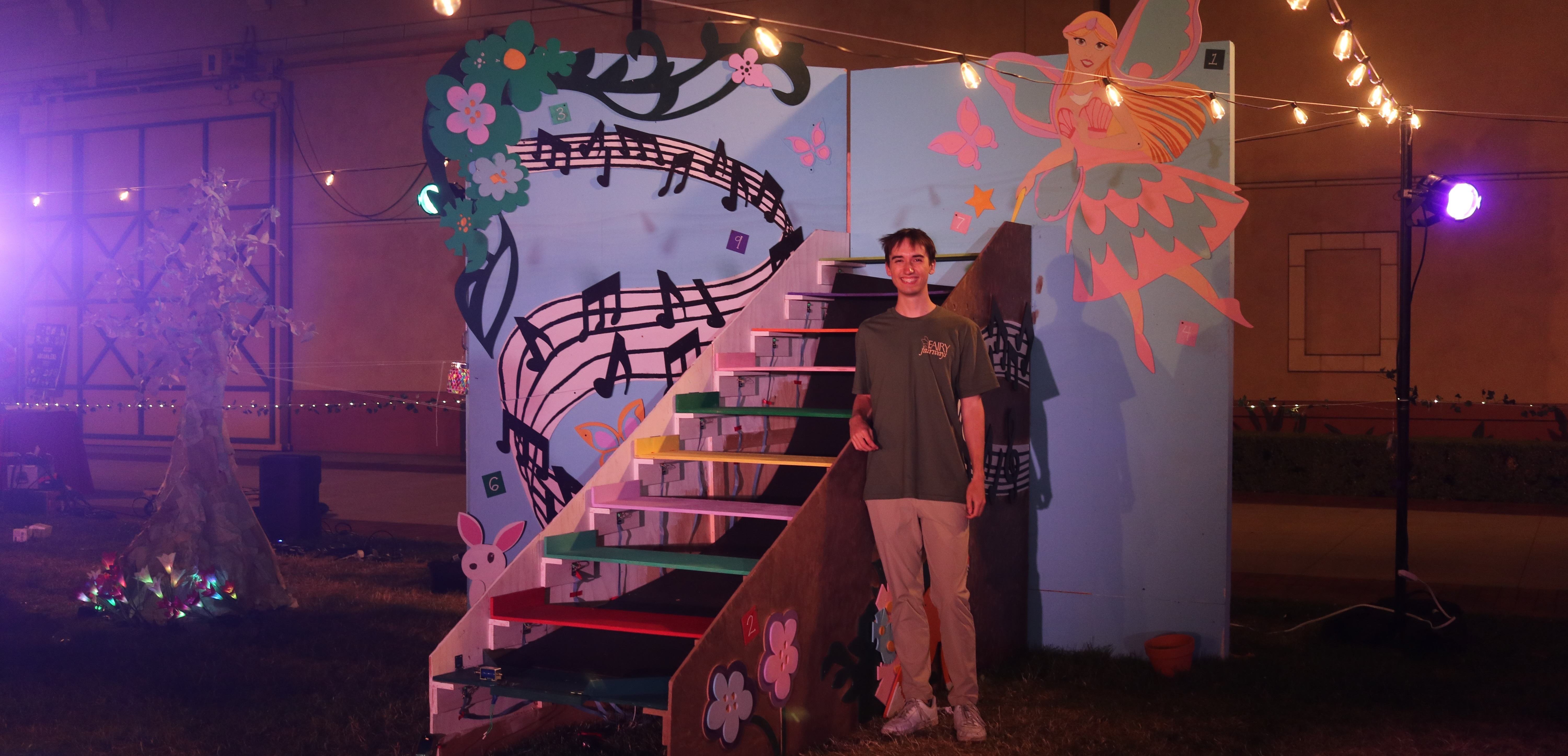
One of the signature courses in USC’s Themed Entertainment program is a year-long miniature golf project, where students design the course in the fall and build it in the spring. Although I wasn’t enrolled in the class, I was brought on as a volunteer technical director to create the embedded system for an ambitious, puzzle-based hole called Musical Steps.
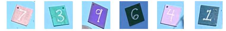
The course was themed as an enchanted garden inhabited by mischievous fairies, with each hole presenting a playful, tricky challenge. In Musical Steps, players encounter a staircase with steps that each play a musical note—but in the wrong order. Their task is to rearrange the steps based on subtle, color-based clues hidden throughout the environment.
My role was to bring this creative concept to life and ensure the experience delivered on its interactive intent.
And, spoiler alert, it worked!
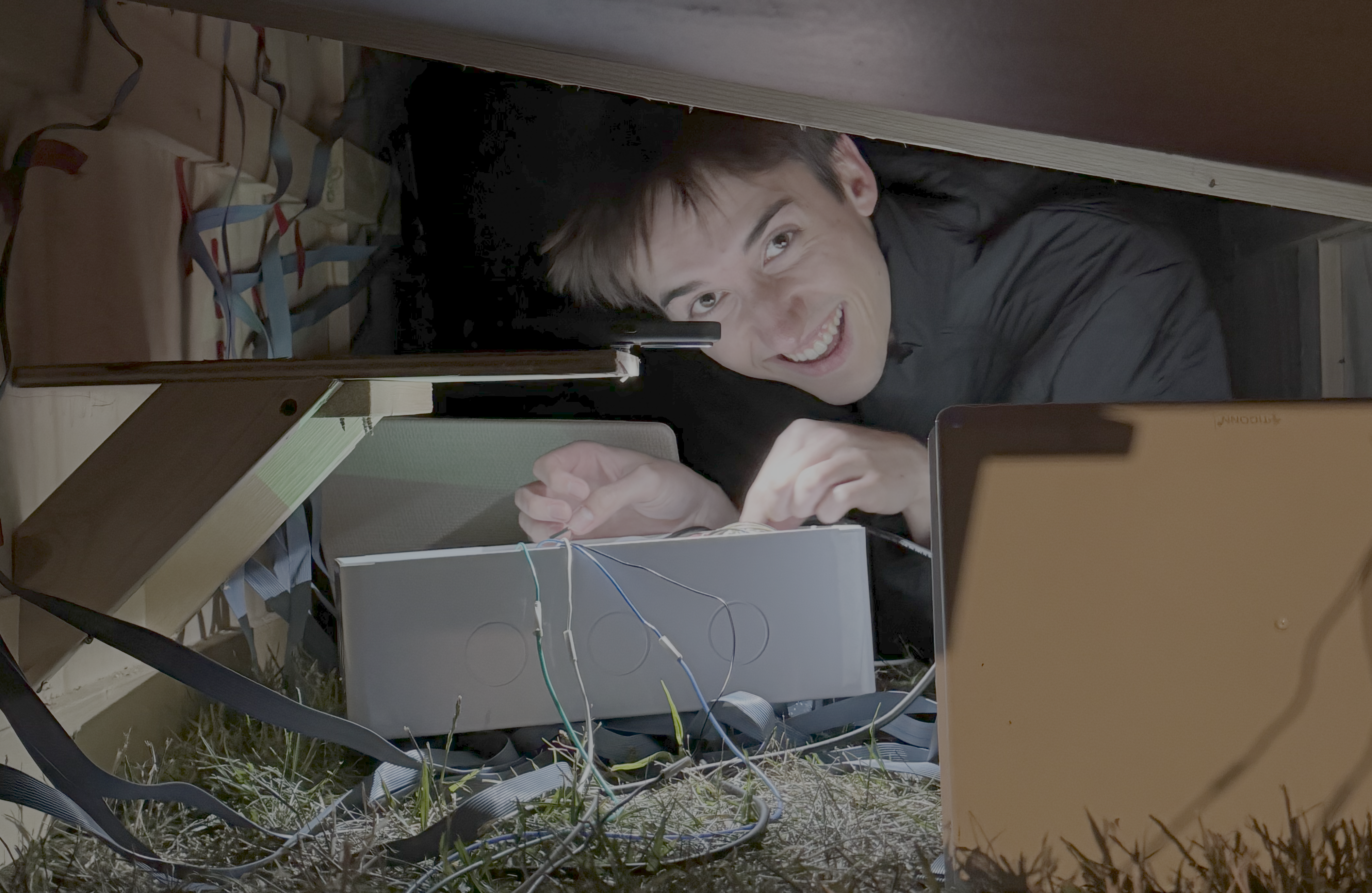
What I initially thought would be a relatively simple project turned out to be the most involved undertaking of my senior year. After countless hours spent troubleshooting out on the lawn where the course was installed, I came away with a deep appreciation for modularity, simplicity, and most importantly, proper desks.
Here’s a quick look at how it works:
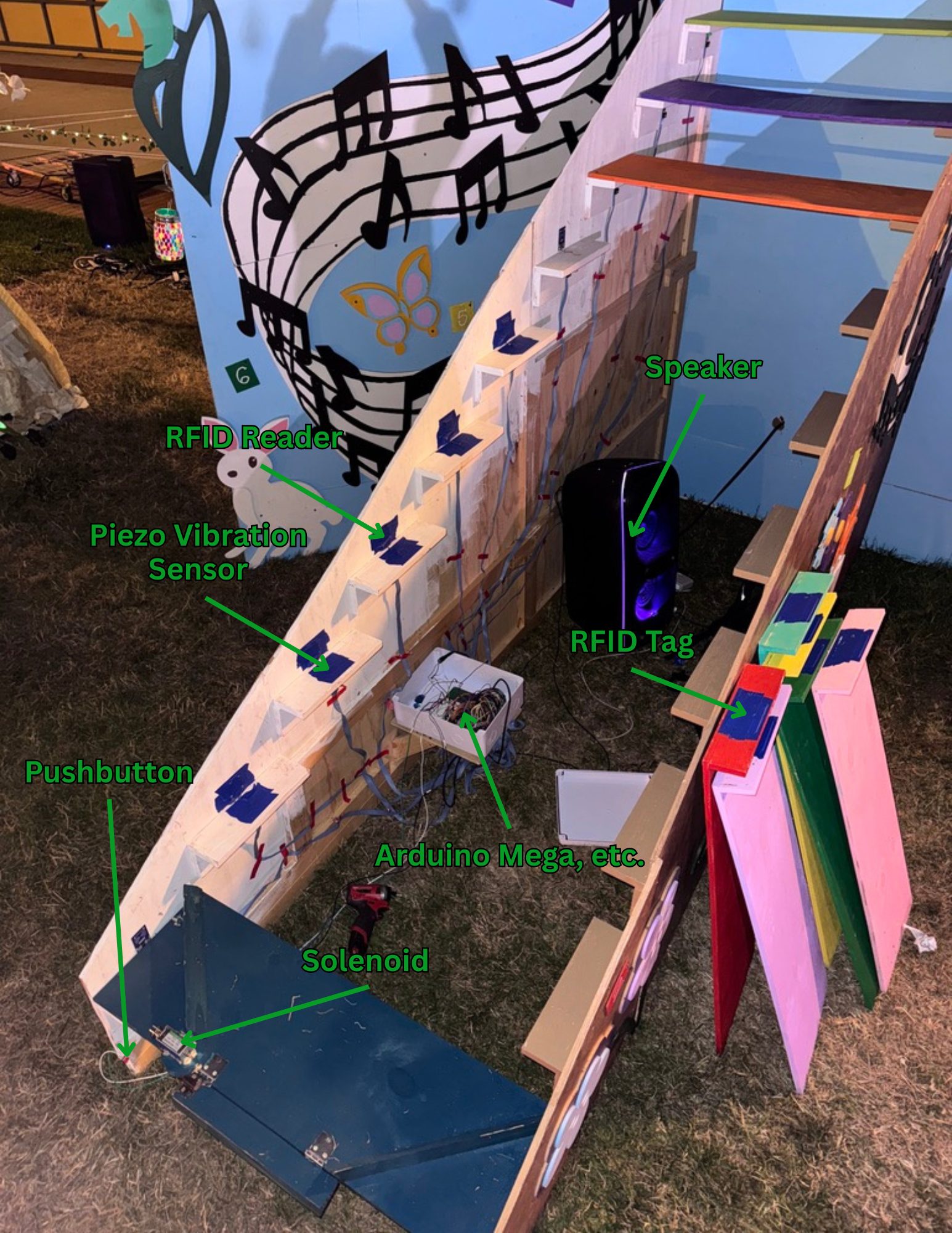
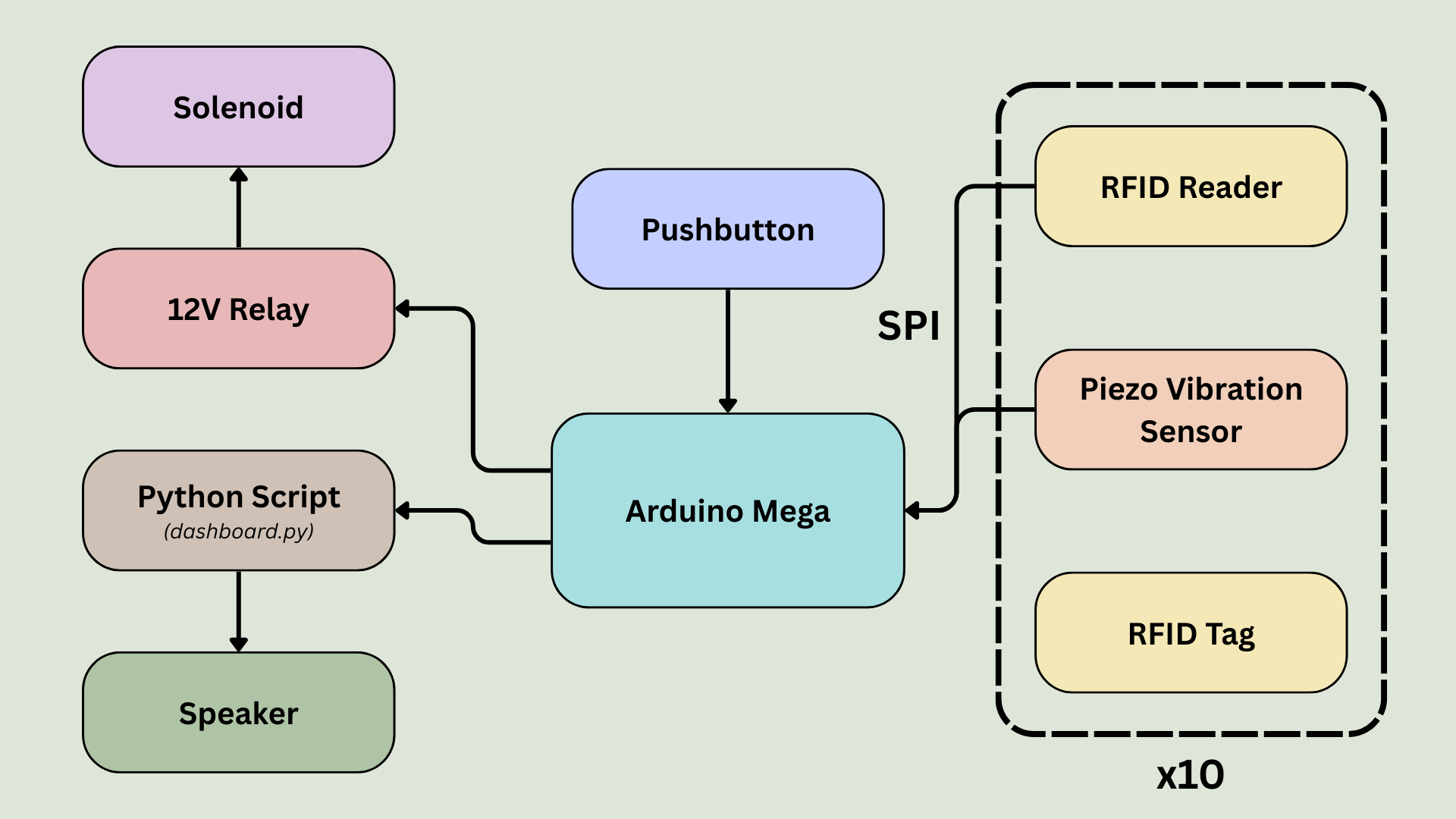
- A "step triggered" event is detected using a piezo vibration sensor on each step platform.
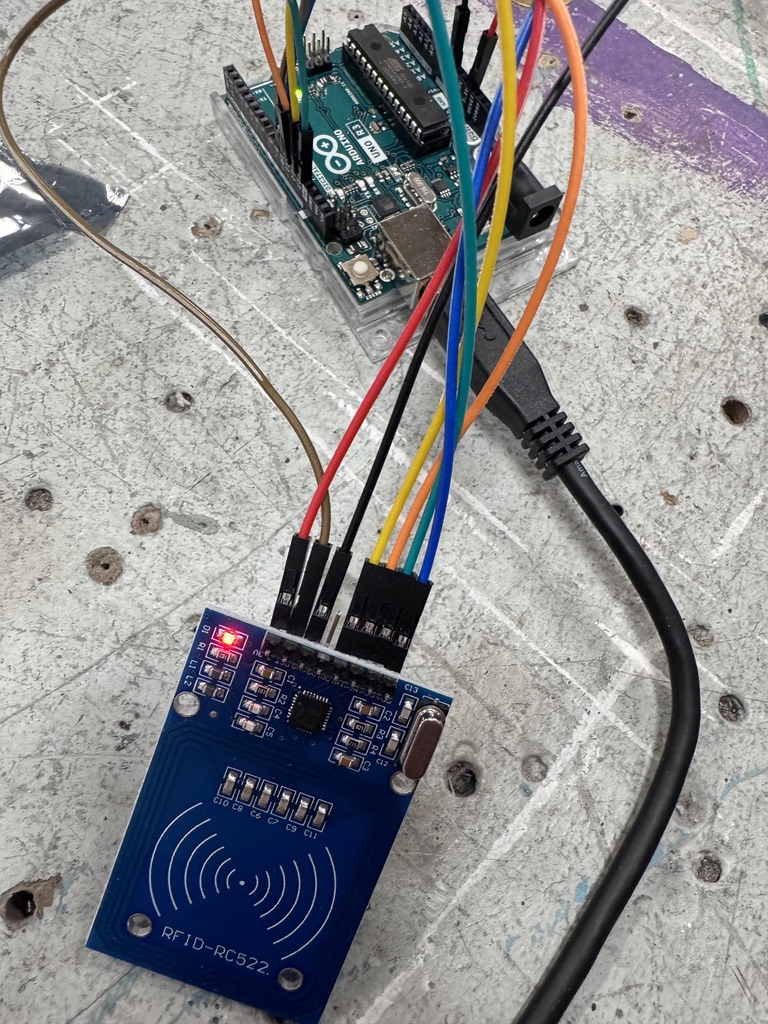
- Each step contains an RFID tag, and each step platform is fitted with a corresponding RFID reader. This tracks where steps are placed.
- A Python script displays the status of each component and sends audio output to a speaker. The Python script receives status and audio messages from the Arduino Mega via serial communication.
- When a step is placed correctly, it plays a musical tone when triggered. When a step is placed incorrectly, it plays a dissonant chord.
- When all steps are placed correctly and the final step is triggered, a solenoid releases a trapdoor. The solenoid is controlled with a 12V relay.
- A pushbutton toggles the solenoid and resets the internal game logic, allowing operators to prepare the hole for the next party.
I followed a workflow of unit testing new components individually and integrating them incrementally through small, iterative steps. That said, a few moments called for a bit more scrappiness and improvisation.
The Biggest Technical Challenges
Assembly and Wire Management
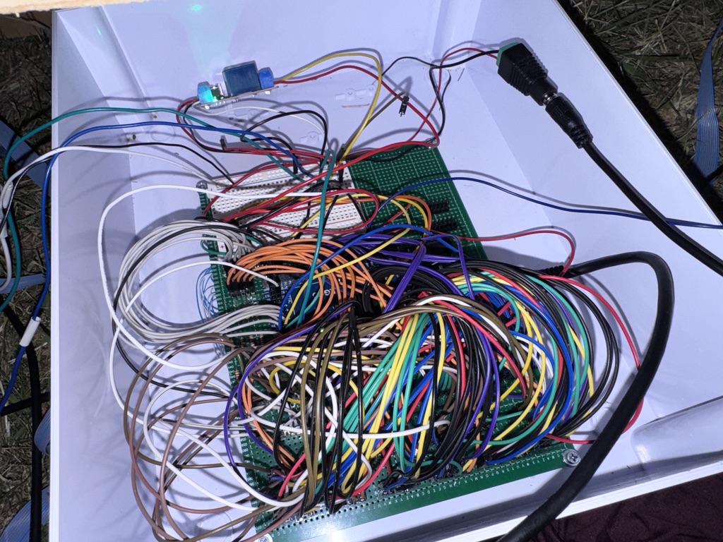
Each musical step includes two electrical components: a piezo vibration sensor and an RFID reader. The piezo requires two wires (GND and Signal), while the RFID reader needs seven (CS, SCK, MOSI, MISO, GND, RST, and 3.3V). By sharing the GND connection, each step requires 8 unique wires, adding up to 80 wires across all 10 steps.
At the start of the semester, I gave myself a week to complete the wiring. But I severely underestimated the complexity of managing that many connections at scale, and it ended up taking over a month.
My initial plan was to run individual wires from the Arduino Mega to each RFID reader and vibration sensor pin. However, this raised two major concerns:
- Cable management: With 80 wires hanging off a physical staircase, the setup would be messy, fragile, and prone to failure.
- Maintainability: If a sensor stopped working mid-operation, fixing it would require a soldering iron and potentially hours of disassembly and rework.
I approached my senior capstone advisor with these concerns, and he suggested using ribbon cable to connect each peripheral step to a central protoboard. If a step failed, its cable could be easily detached, making component replacement quick and straightforward.
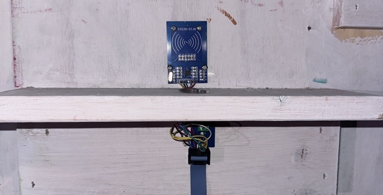
As a result, wiring up a single step became an hours-long process. For each one, the ribbon cable had to be carefully measured, cut to length, and crimped onto connectors. On the step side, eight wires were measured, cut, stripped, soldered to their respective components, and threaded through small holes in the step platform. The RFID reader was mounted to the wall, and the piezo sensor was adhered directly to the step.
On the protoboard side, pin headers were cut and soldered in place, both for each ribbon cable and for the shared signals (MISO, MOSI, SCK, RST, GND, and 3.3V). Only after all of this could the sensors be connected to the Arduino Mega for integration testing.
If I had done this alone, it would have taken days. But fortunately, other team members were eager to help. I created a series of step-by-step instructions to guide them through assembling and testing each component. Here’s an example for the piezo vibration sensors.
Audio Delay
This issue didn’t surface until the system was fully integrated. But by that point, several sources of audio delay had become apparent.
Initially, the speaker was controlled directly by the Arduino Mega via a serial MP3 player module. These modules require MP3 files to be preloaded onto a microSD card and accept traditional commands like Play, Next, and Back. However, the onboard processor introduces noticeable latency when handling these commands, resulting in a delay between when a step is triggered and when the corresponding tone is played.
Further delay came from the software-implemented SPI communication with the RFID readers, as described in the previous section. While this bit-banged SPI allowed for reliable long-distance communication, scanning all readers could take up to 4 seconds. Because the Arduino Mega is single-threaded, this would sometimes delay tone playback by several seconds.
To reduce these delays, I implemented three key solutions:
- Replaced the MP3 module with a Python script: By routing audio playback through a Python script over serial (at 9600 baud), the system became significantly more responsive.
- Reduced RFID polling frequency: Instead of scanning continuously, RFID readers are polled every 10 seconds. This has minimal impact on gameplay, as players typically take longer than that to place a step and prepare for the next action.
- Paused scanning during final play: Once the steps are arranged correctly, RFID scanning is suspended until the game is reset. This ensures that audio feedback is immediate during the most crucial and satisfying moment: the player’s victory attempt.
Operation
The mini-golf course operated continuously over the span of a full day, so it was important to make the system as simple and intuitive as possible for operators to manage. This led to two key design decisions:
- A physical reset button: Pressing this pushbutton resets all internal game state variables and toggles the solenoid, allowing the operator to easily re-close the trapdoor between rounds.
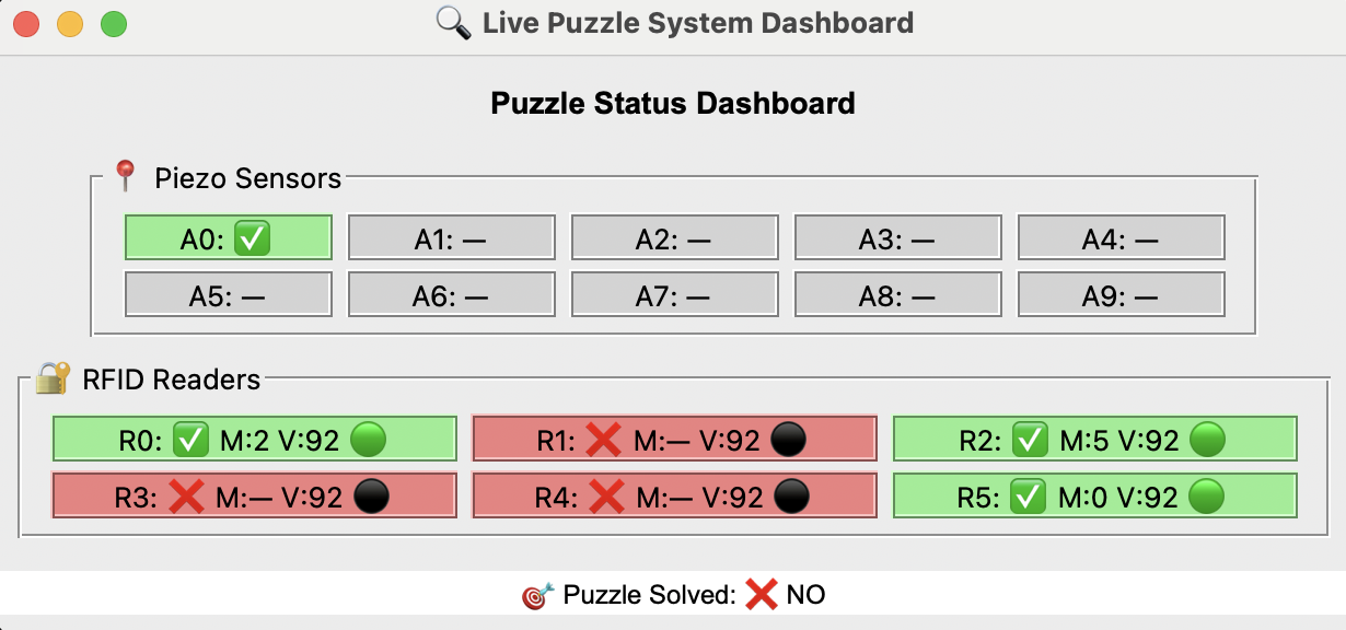
- A real-time GUI: A simple graphical interface was created to display the status of each step and its components. This GUI was integrated into the Python script responsible for audio playback, as described in the previous section.
Long-Range SPI
The RFID readers communicate using the SPI protocol. SPI was originally designed for short-distance, high-speed communication on a single PCB. However, Musical Steps required SPI to function reliably over distances of up to seven feet, well beyond its intended range.
This limitation was a known concern from the outset and became a central focus of early unit testing. In those tests, I found that the RFID readers operated reliably at short distances or in small groups, but began to fail and become unresponsive when the wiring extended beyond four feet.
I achieved early success by combining several signal integrity strategies:
- Reducing the SPI clock speed from 1 MHz to 500 kHz.
- Adding 100Ω series resistors on the SCK, MOSI, and CS lines to dampen reflections.
- Alternating GND and signal lines within each ribbon cable to minimize crosstalk and ensure clean return paths.
With these improvements, I was able to reliably operate two RFID readers simultaneously over distances of up to 7 feet.
But scaling beyond that, even to three readers, remained unreliable.
I tried just about every trick in the book: adjusting clock speeds further, experimenting with multiple RFID and Software SPI libraries, and even borrowing Professor Allan Weber’s portable oscilloscope to diagnose the issue.
One idea remained. Since I had verified that the readers worked reliably in pairs, I theorized that I could run SPI over five independent sets of Arduino pins: one for each pair of readers. The catch? I could no longer use the Arduino’s built-in hardware SPI library.
So, I painstakingly rewrote the entire SPI communication for the RFID readers in software.
And, it worked! With a bit-banged implementation of SPI, long-range communication was no longer an issue. The RFID readers responded reliably, even at full distance.